Choosing Handrail Elbows and Connectors
Handrail connectors link the separate rail lengths, branches and terminations in a railing layout. An elbow changes direction, an offset moves the rail line, a tee adds a branch and a sleeve joins a particular mating interface. These functions should be identified before material and finish are selected. Foundry Queen groups thirteen reference configurations by their actual geometry and coupling information. Keep each product reference with the selected drawing so its image and dimensions remain connected. A single fitting photograph does not establish the performance of a complete handrail or railing system.
Begin with the Complete Rail Layout
Show the handrail run, corners, branches, supports and ends in one layout. Identify where each reference fitting will be used and which direction its connections must face. Include slopes, changes in level and any restricted access near the building or adjacent glass. The layout helps distinguish an angled connector from a true right-angle corner and a return from an open end elbow. Keep drawing revisions clearly labelled. A list of quantities without locations can leave the orientation of similar-looking parts unresolved.
Match Diameter and Wall Thickness
The reference selection includes 38.1, 42.4 and 50.8 mm coupling information. Some entries also state a 1.5 mm tube wall reference. Confirm the actual external and internal tube dimensions, not only the nominal diameter in a product name. The insertion section needs to match the tube interior and provide the engagement required by the selected assembly. Check shoulders, stops and securing positions on the part drawing. Two products with a similar outer appearance can still have different mating dimensions or end arrangements.
Right Angle Handrail Elbows
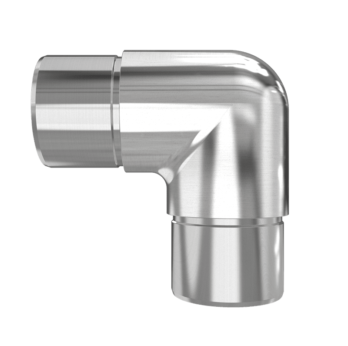
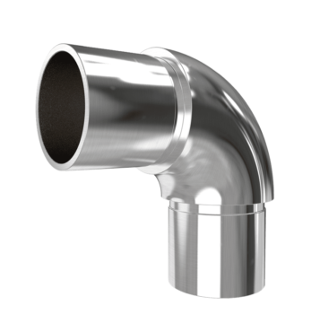
The HR-3890 and HR-5090 references use a right-angle body with projecting insertion sections at both ends. The listed mating sizes are 38.1 by 1.5 mm and 50.8 by 1.5 mm respectively. Review the corner footprint, visible shoulder and tube engagement together. Confirm whether the adjacent rail lengths can be assembled and secured with the available access. Diameter identifies an important difference between these versions, but it should not be treated as a structural rating. Keep the selected material and finish with the dimensioned configuration.
Slotted Profile Elbow Connections
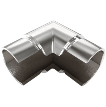
The HR-3890VS reference has open slotted sections through a right-angle connection and lists a 38.1 by 1.5 mm mating profile. Match the slot position and opening dimensions as well as the round exterior. A connector intended for an unslotted tube can engage differently even when the outer diameters are similar. Identify the slot orientation around the corner and show the adjacent components on the drawing. Confirm how the junction will be secured and whether any additional components form part of the supplied configuration.
Offset Handrail Connections
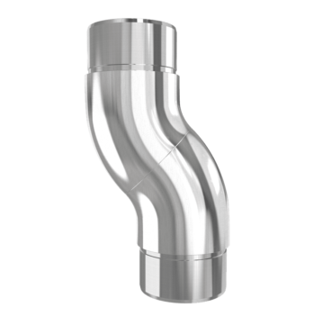
The LHR-50SA reference creates an offset between its round tube ends using two curved sections. Its listed mating size is 50.8 by 1.5 mm. The offset distance, connection orientation and available clearance need to be confirmed on the selected drawing. Do not replace it with a single elbow merely because both products contain curved sections. Show the required rail lines and the reason for the offset in the layout. Check that assembly access, securing positions and adjoining finishes remain practical at that location.
Adjustable Round Elbow Arrangements
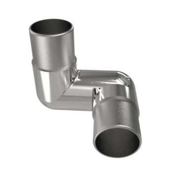
The LS-AJ9038V reference connects two round ends through an articulated centre and lists a 38.1 mm coupling. Specify the required direction and angle in the rail layout. Confirm the actual adjustment plane, permitted setting and securing arrangement for the supplied version. The product image shows a position of the joint, rather than proving an adjustment range or an installed capacity. Include any constraints at nearby walls, panels or supports when requesting the fitting. Keep the selected joint orientation with its product code and drawing.
Curved and Angled 42.4 mm References
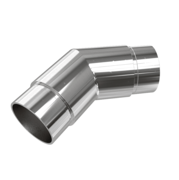
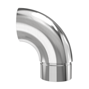
The LS-NTR-R42.4-6 reference uses a curved elbow body, while LS-NTR-R42.4-8 has an angled direction-changing body. Both list 42.4 mm coupling information, but their geometry should be compared separately. Confirm the included angle and the way each insertion end meets the adjacent tube. A general description of an elbow is not enough to select between them. Use the actual layout and part drawing to resolve the orientation, corner footprint, insertion engagement and securing details before the order is confirmed.
Three Way Corners and T Junctions
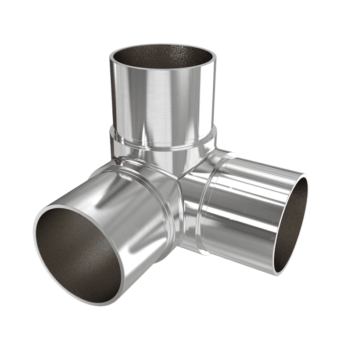
LS-NTR-R42.4-9 connects three directions around a compact corner body. LS-NTR-R42.4-10 is a T-shaped junction that adds a branch to a straight run. Both list 42.4 mm coupling, but they perform different jobs in the rail layout. Mark the required directions at the junction and show which rail continues through it. Confirm how the associated rails and supports will be assembled. Avoid selecting a three-way fitting by the number of openings alone; the spatial arrangement of those openings matters.
Open End Elbow References
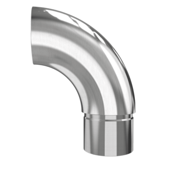
The HR-38EE and HR-50EE references combine a curved end section with an insertion connection. Their listed mating sizes are 38.1 by 1.5 mm and 50.8 by 1.5 mm respectively. Confirm the open end arrangement, curvature and connection direction on the selected drawing. Identify any additional end treatment required by the project. An open end elbow and a closed return should not be treated as the same product. Keep the final termination detail with the handrail layout so the intended end condition remains clear.
Sleeves and Closed Returns
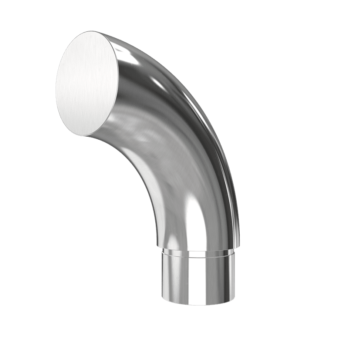
The HR-38SJ reference is an open-sided sleeve with two visible set-screw positions and a listed 38.1 mm coupling. Review its opening and mating interface before choosing it for a connection. The LS-NTR-R42.4-12 reference instead forms a curved return with a closed circular end and a listed 42.4 mm coupling. Confirm the return direction and clearance at the termination. These two configurations illustrate why the actual product image and reference drawing need to take priority over a broad category description.
Choose Material and Finish Together
The referenced families list stainless steel grade and finish options, with the supplied version to be confirmed for each order. State the installation environment and any cleaning or exposure requirements. Review adjoining materials, fasteners and visible finishes at the same time. A polished or black surface does not identify the underlying grade or prove a particular service life. Where appearance matching is important, agree a finish reference or sample. Keep finish approval separate from the dimensional review so that a decorative choice does not hide an unresolved fit.
Build a Consistent Product Schedule
For each fitting, record its product code, position in the layout, mating tube dimensions, wall thickness, quantity and orientation. Add selected material, finish and any required securing components. Include the supplied or cut lengths of adjacent rails if those form part of the enquiry. State the delivery destination and identify documentation needs before the quotation is finalised. Reference unit weight can help identify a product or discuss packing, but it is not an allowable load. Keep the complete schedule and drawing revisions together for review.
Confirm Before Ordering
Review the final selected drawing, coupling fit, insertion engagement, corner direction and end condition before ordering. Confirm which components are included, how each junction will be secured and which dimensions remain project-specific. Product references should match the actual fitting supplied rather than a similar-looking photograph. Any installation limits or performance evidence need to relate to the selected complete arrangement. Use the linked detail pages to keep the relevant images and configuration information together, then send Foundry Queen the layout, quantities and selected finish for a focused product enquiry.
Send the handrail connector schedule to Foundry Queen.