Choosing Glass Spigots for Railing and Fence Projects
Start with the complete glass assembly
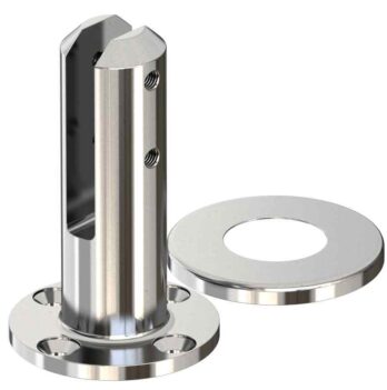
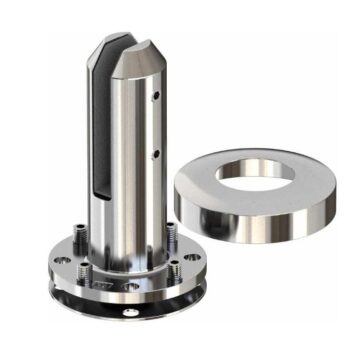
Glass spigots provide a compact connection between a panel and its supporting construction. Their short visible body can make different products look interchangeable, yet the jaw, insert, mounting stem and base plate can differ substantially. Start with the panel schedule and a section through the support. Identify the glass build-up, exposed height, panel width, joint positions and substrate before choosing a decorative finish. Foundry Queen enquiries can then refer to a specific component and drawing. A catalogue photograph does not establish the capacity of the whole barrier, and a nominal glass thickness does not define the correct insert or fixing arrangement.
Separate surface mounting from core mounting
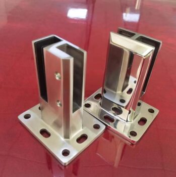
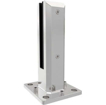
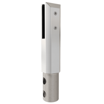
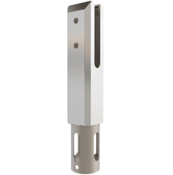
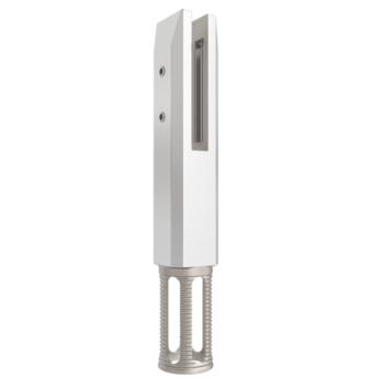
Surface-mounted spigots use an accessible plate fixed to a suitable support. Their fixing footprint, cover and installation access must be considered together. Core-mounted versions instead continue below the visible body through a stem, often with threads or elongated openings. That difference changes the concealed construction detail. Do not substitute a core-mounted fitting for a base-plate version because the upper jaw appears similar. Confirm the core pocket, embedment, setting material and finished level with the responsible project designer. Keep waterproofing, drainage, edge distances and surrounding finishes visible in the assembly drawing so they are reviewed before glass is ordered.
Compare square base configurations
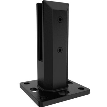
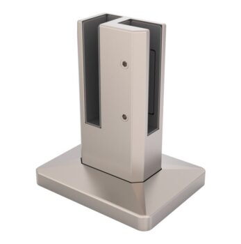
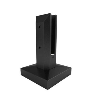
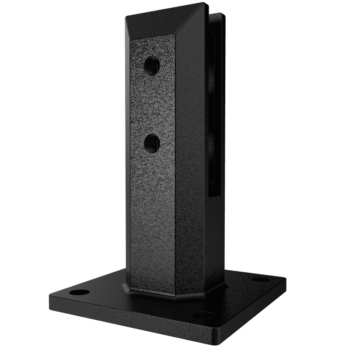
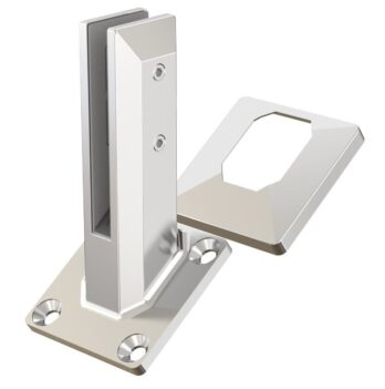
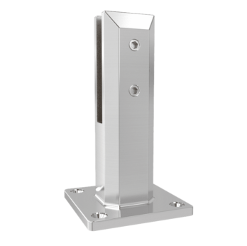
The 188SD square surface mount family provides a starting point for a conventional square-base arrangement. Other square families, including LS-ASF and ADJ-STR-GS, have their own references and dimensions. Their plate outlines, screw locations and covers should be matched to the intended installation. Black and polished LS-ASF photographs represent finish versions of one model, so they are grouped on one product page. This avoids confusing colour with geometry. Ask for the selected drawing and an accessory list, then compare the available mounting area and glass clearance with the actual building detail.
Coordinate straight joints and corners
The DOSD-90 corner spigot serves a different panel junction from the DOSD-180 straight-through arrangement. Show both panels and their joint in plan when asking about either configuration. Review the glass edge clearance, relative panel positions and access to each clamping screw. A corner location can restrict the available anchor footprint or tool access even when a fitting appears suitable in isolation. Confirm how the surrounding panels will be set out and aligned. The panel schedule and fixing drawing should identify which reference belongs at every corner or straight joint.
Choose round bodies by reference
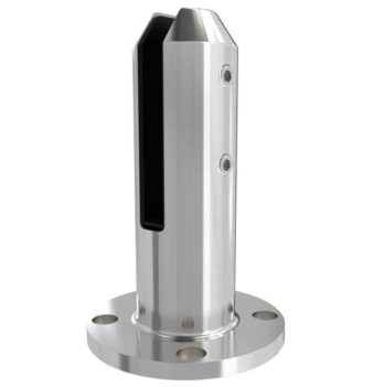
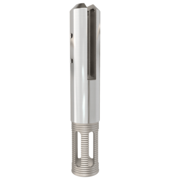
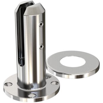
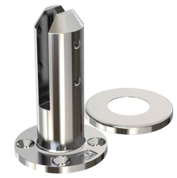
Round spigots include LS-ARF, LS-BRF, LS-CRF and LS-DRF base-mounted families. Similar cylindrical bodies do not mean the bases, inserts or listed glass ranges are the same. Compare the complete model rather than treating all round products as one option. A circular cover can conceal fixing positions after assembly, but installation access must remain available until alignment and tightening are finished. Specify the body and base dimensions and confirm the selected cover. Where the glass build-up is laminated, identify its complete nominal thickness and the required insert, including the specific configuration proposed for the order.
Review the core-mounted families
LS-ASC, LS-BRC, LS-BSC, LS-NRC, LS-OSC and 188SC285 use different square or round upper bodies and concealed lower stems. Compare the stem diameter, opening arrangement and required embedded length on the selected drawing. Establish the finished surface level so the visible jaw engages the glass at the intended height. An elongated stem opening is a geometric feature, not a complete installation specification. The core preparation and fixing method must be compatible with the actual supporting construction. Retain the component reference with the installation section and confirm the supplied insert, setting components and cover scope before approving the order.
Allow for height and slope adjustments
The AHD-1 height-adjustable spigot, ASD-3-S base-adjuster configuration and LS-FRF-90 shim-adjustable family address different alignment needs. Identify what must move, in which direction, and by how much. Do not assume that one adjustment mechanism can correct every substrate or panel tolerance. Confirm the adjustment sequence and final locked condition with the selected drawing. The ADJ-BVL-GS stair family is listed with three bottom-pad configurations; specify the required slope and pad rather than assuming a continuously variable angle. Coordinating these details early helps keep the glass order and support positions consistent.
Identify side mounting separately
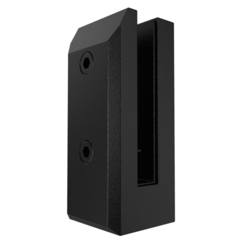
The ADJ-GW-GS side-mounted spigot places the fixing support beside the glass rather than directly below it. Its compact rectangular body should therefore be reviewed in section through the edge condition. Check access for fixings and clamping screws, the available structural face and the relationship to adjacent finishes. A side-mounted configuration may be useful where a floor plate is unsuitable, but the project designer must still establish the complete support arrangement. Identify glass clearances and the proposed installation sequence before selecting the visible finish. Keep this mounting family separate from core and floor-base alternatives in the schedule.
Match the glass to the insert
Many families list 8, 10 or 12 mm glass, while LS-DSF lists a 12–15 mm range and LS-DRF includes additional laminated thickness references. These ranges describe model options, not permission to use any panel with any insert. State whether the panel is monolithic or laminated and provide the complete build-up. Confirm jaw engagement, contact materials, edge treatment and required glass preparation with the selected assembly. Do not infer drilling requirements from a generic product title. The approved glass drawing and fitting drawing should agree before fabrication proceeds, particularly where a project combines several spigot families.
Specify material and appearance together
Material grade and surface finish serve different purposes and should be recorded separately. Stainless steel options and decorative finishes must be confirmed for the selected model and exposure conditions. Identify outdoor, poolside or other demanding locations in the enquiry rather than choosing from colour alone. When appearance matters, agree a finish sample and compare it with adjoining metal components. A polished product image cannot guarantee the final supplied colour, gloss or maintenance requirements. Record the agreed grade, finish reference, sample approval and handling requirements with the quotation so decorative expectations do not replace the dimensional and installation review.
Check covers, fixings and supply scope
A product photograph may show a cover or adjustment component without defining everything supplied. Ask for a clear list of inserts, screws, covers, pads and other accessories. Confirm anchors and installation materials individually; they depend on the supporting construction and should not be assumed from the spigot image. Review packing so visible surfaces and matching components remain identifiable on delivery. Keep model references on the panel schedule and separate finish choices from dimensional variants. Where several families are ordered for one project, identify their locations and quantities explicitly to reduce the risk of parts being mixed during installation.
Prepare a clear Foundry Queen enquiry
Send a layout, relevant sections, panel dimensions, glass build-up, mounting arrangement, proposed substrate, quantities, material and finish requirements, and delivery destination. Include corner, stair and edge conditions that cannot be understood from a single fitting photograph. Use the Construction Material range to compare adjoining glass hardware, and follow the individual product pages for model-specific reference information. The Foundry Queen contact page provides the enquiry route. Confirm the drawing revision and complete supply scope before ordering, with final assembly performance and local project requirements reviewed by the responsible professionals.