 By Coco
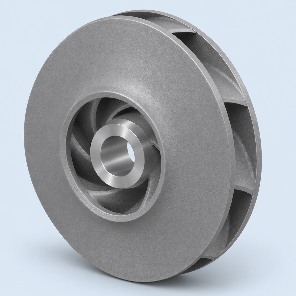
Impeller vs propeller is a useful comparison when identifying rotating components, but neither name provides a complete manufacturing specification. An impeller commonly operates within a machine’s fluid-handling arrangement, while a propeller is often associated with moving fluid around exposed blades. The exact application and assembly determine what must be supplied.
Begin with the surrounding machine
Identify the pump, fan, mixer, vessel or other equipment in which the rotor will operate. Include the original part reference where available. A supplier needs to know whether the request is for an approved replacement, a development sample or a new design.
Describe what is included in the order. A casting blank, a machined rotor and a balanced ready-to-install assembly have different acceptance requirements. The product name should not silently decide which of those conditions is intended.
Compare geometry without inferring performance
Blade shape, hub arrangement and surrounding passages affect how the component fits and functions. A photograph can help identify a type, but it cannot establish a performance curve, efficiency or cavitation behavior. Those require appropriate design and testing information.
The impeller component category includes different rotor arrangements. A custom open pump impeller is a product type for discussion, not a universal substitute for another rotor with a similar diameter.
Make interfaces explicit
Specify the shaft connection, bore, keyway, mounting faces and direction references on a controlled drawing. State the datum system used to relate those features to the blades. A rotor can have an acceptable exterior form and still fail to fit its intended shaft.
For a replacement part, clarify whether the existing assembly or a nominal drawing defines the requirement. Worn mating components may not represent the original design condition. Any decision to reproduce a worn interface should be reviewed rather than made by the manufacturing supplier.
Connect material and manufacture to service
Provide the fluid or environment, temperature range and relevant wear or corrosion conditions to the responsible designer. Select the material specification accordingly. The same component shape may be manufactured from different alloys for different duties.
Discuss whether casting, machining or a combined route is appropriate for the geometry and quantity. Complex blade passages can change tooling, core and cleaning requirements. A process recommendation should follow the actual model instead of a blanket claim that all impellers or propellers use one route.
Example: a rotor copied from an external scan
An external scan may capture blade appearance while omitting a bore, keyway or internal passage detail needed for manufacture. Before treating the scan as a production model, reconcile it with the controlled interface and verification requirements. A rotor that fits the visible envelope may still be unsuitable for the shaft or machine. Identify uncertain data rather than letting the supplier invent missing geometry.
Agree final verification
Separate dimensional inspection from balance and performance verification. State any balance requirement, reference condition and responsible party explicitly; do not assume balancing is included with the raw casting. Likewise, a dimensional report does not demonstrate the required fluid performance.
For sample orders, define what the trial must prove and what records are required before repeat production. Keep changes to blades, hub and interfaces synchronized in the revision history. This prevents an approved sample from becoming an ambiguous reference after design changes.
Enquiry checklist
| Item | Information needed |
|---|---|
| Machine context | Application, original reference and delivery condition |
| Interfaces | Bore, shaft connection, datums and rotation references |
| Verification | Dimensions, specified balance scope and functional testing responsibility |
For Foundry Queen enquiries, compare the relevant propeller and turbine component pages and submit the controlled drawing. Geometry identifies the component; evidence establishes acceptance.
Technical reference
SFSA: Steel Castings Handbook, Supplement 2. This reference provides technical context; it does not establish Foundry Queen certification or project approval.
Get Premium Casting Products
Join FoundryQueen.com Newsletter to get more information of different premium OEM Casting products in China.