 By Coco
Spider glass fittings connect point-supported glazing to a supporting structure through several coordinated components. The visible arms are only part of the arrangement; panel interfaces, joints and structural attachments also need definition. This Foundry Queen article provides an enquiry framework, rather than a calculation method or approval for a particular glazed assembly.
Separate the arm from the glass connection
A spider assembly may involve an arm body, a point fixing at the glass and a connection to the support. Their geometry and permitted movement must work together. Counting the arms in a photograph does not identify the complete assembly or its design capacity.
Ask for a component drawing that names each item and shows its relationship to the panel. Confirm which pieces are included in the quoted assembly and which must be supplied by another party. This is particularly important when a catalogue photograph includes accessories that are not part of the order.
Describe the panel layout and movement
Provide the panel arrangement, joint positions and support layout. State which locations are corners, edges or internal intersections. The system designer must consider the actual loads and movements, including the behavior of the supporting structure.
Do not prescribe a universal glass thickness or hole position from a generic article. Glass preparation needs to match the selected point fixing and approved glazing design. Obtain the precise drawing before the panels are manufactured, and keep hardware substitutions under revision control.
Do not confuse standoffs with spider assemblies
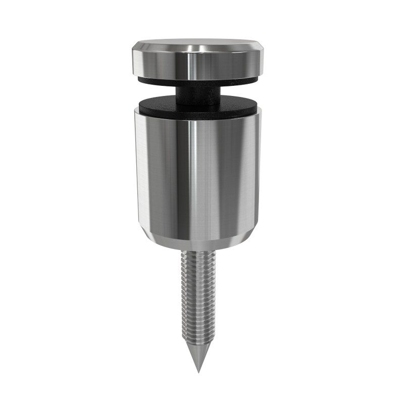
Point-supported hardware includes several product families. Our glass standoff pins and STDC-4 standoff example demonstrate identifiable fixing components, but they are not presented as interchangeable spider systems.
Use a related catalogue page to communicate an interface or appearance preference, then label it clearly as a reference. If a custom spider arrangement is needed, request feasibility confirmation for the complete drawing. A supplier should not infer the required assembly from an unrelated link.
Define material, finish and evidence
State the specified material and surface condition for every component, including concealed pieces. A polished appearance does not prove the alloy, and a single material description may not apply to all parts of an assembled fitting. Request traceable documentation where the project requires it.
Identify the evidence needed from the product supplier and the evidence needed from the glazing designer. Material records, component dimensional inspection and complete-system engineering answer different questions. Keeping them separate avoids treating one certificate as proof of every aspect of the installation.
Example: a reference fitting sent without a layout
A buyer sends a photograph of a four-arm fitting and requests several pieces. The image does not establish panel positions, glass preparation, joints or the support connection. A useful response is a request for the coordinated layout and component drawing, not a guess at the complete assembly. Label reference images as references and confirm the actual supply requirement before a sample or quotation is approved.
Control samples and changes
For a custom project, a sample may be useful to check interfaces, appearance and assembly access. Define those objectives before the sample is produced. A successful bench assembly does not replace structural verification or site-specific approval.
Approve changes through a revised drawing and bill of materials. Keep the mating parts, glass preparation and support detail synchronized. An apparently minor thread or washer change can affect the interface even when the visible arm remains unchanged.
Enquiry checklist
| Enquiry document | Purpose |
|---|---|
| Panel and support layout | Defines locations and joint arrangement |
| Assembly drawing | Identifies arms, point fixings and mating pieces |
| Responsibility list | Separates product evidence from system approval |
Discuss the required component scope with Foundry Queen. Confirm actual product availability and project requirements before treating reference hardware as a complete system quotation.
Get Premium Casting Products
Join FoundryQueen.com Newsletter to get more information of different premium OEM Casting products in China.